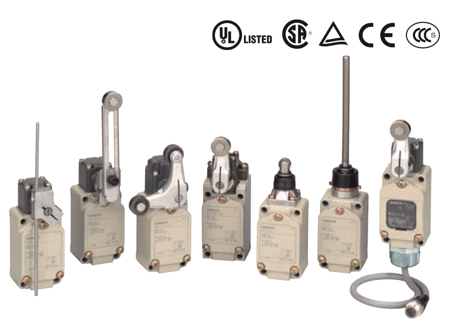
Ratings / Characteristics

Ratings

Rated voltage Rated 
voltage 
(V)
Non-inductive load (A) Inductive load (A)
Resistive load Lamp load Inductive load Motor load
NC NO NC NO NC NO NC NO
WL[]-LES 125 VAC 
250 VAC
10 
10

2
1.5 
1
10 
10

5

5
WL[]-LDS

115 VAC

10 3 1.5 10 5 2.5
12 VDC 
24 VDC 
48 VDC
10 

3


2


1.5
10 

3


2

Note: 1. The above figures are for steady-state currents.
2. Inductive loads have a power factor of 0.4 min. (AC) and a time constant of 7 ms max. (DC).
3. A lamp load has an inrush current of 10 times the steady-state current.
4. A motor load has an inrush current of 6 times the steady-state current.

Characteristics

Degree of protection IP67
Durability 
*1
Mechanical 15,000,000 operations min. *2
Electrical 750,000 operations min. *3
Operating speed 1 mm/s to 1 m/s (in case of WLCA2)
Operating 
frequency
Mechanical 120 operations/minute min
Electrical 30 operations/minute min.
Rated frequency 50/60 Hz
Insulation resistance 100 MΩ min. (at 500 VDC)
Contact resistance 25 mΩ max. (initial value for the built-in switch when tested alone) *6
Dielectric 
strength
Between terminals of the same 
polarity
1,000 VAC, 50/60 Hz for 1 min
Between current-carrying metal 
part and ground
2,200 VAC, 50/60 Hz for 1 min/Uimp 2.5 kV
Between each terminal and non- 
current-carrying metal part
2,200 VAC, 50/60 Hz for 1 min/Uimp 2.5 kV
Rated insulation voltage (Ui) 250 V (EN60947-5-1)
Pollution degree (operating environment) 3 (EN60947-5-1)
Short-circuit protective device (SCPD) 10 A, fuse type gG or gI (IEC60269)
Conditional short-circuit current 100 A (EN60947-5-1)
Conventional enclosed thermal current (Ithe) 10 A, 0.5 A (EN60947-5-1)
Protection against electric shock Class I
Vibration 
resistance
Malfunction 10 to 55 Hz, 1.5-mm double amplitude *4
Shock 
resistanc
Destruction 1,000 m/s2 max.
Malfunction 300 m/s2 max. *4
Ambient operating temperature -10°C to +80°C (with no icing) *5 
Ambient operating temperature 35% to 95% RH
Weight Approx. 275 g (in case of WLCA2)

Note: 1. The above figures are initial values.
2. The figures in parentheses for dielectric strength are those for the microload models.
*1. The values are calculated at an operating temperature of +5°C to +35°C and an operating humidity of 40% to 70%RH. Contact your OMRON sales representative for more detailed information on other operating environments.
*2. Durability is 10,000,000 operations min. for general-purpose overtravel models, and for flexible rod models. 500,000 operations min. for weather-proof models.
*3. Microload models are 1,000,000 operations min. 500,000 operations min. for weather-proof models.
*4. Except flexible rod models. The shock resistance (malfunction) for microload models is 200 m/s2 max.
*5. For low-temperature models this is –40°C to +40°C (with no icing). For heatresistant models the range is +5°C to +120°C.
*6. For microload models, the contact resistance is 50 mΩ max. (initial value for built-in switch)

Downloads

Document File Type File Size Download
WL Series Datasheet PDF 7.6 MB